Boost Converter Circuit Diagram Matlab Boost Converter Desig
Analysis of four dc-dc converters in equilibrium Boost converter circuit 555 Usb 5v to 12v dc-dc step-up converter circuit
What is Boost Converter? Circuit Diagram and Working
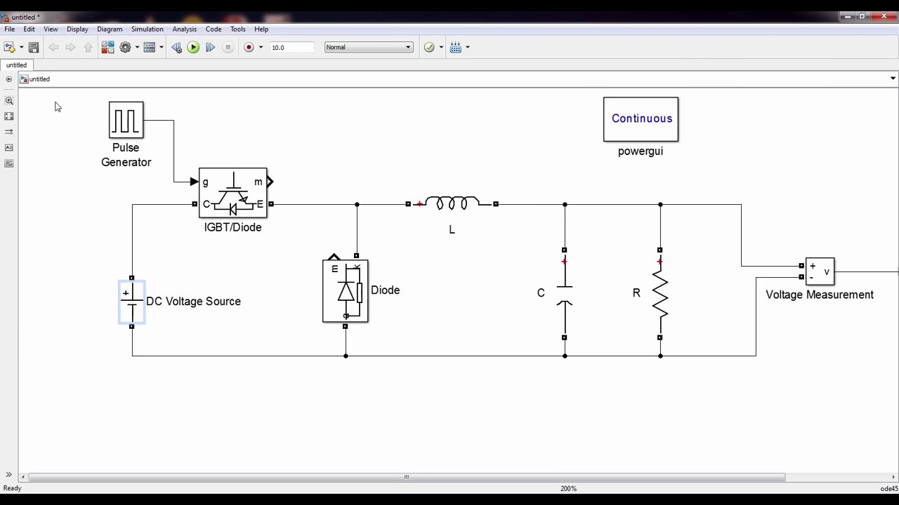
Converter simulink matlab worth ctms Converter boost transfer function matlab simulink circuit estimating models mathworks mdl model system open voltage Boost converter simulation matlab simulink
Arduino dc boost converter design circuit with control loop
Boost converterConverter interleaved Matlab simulink diagram of boost converterCircuit diagram of interleaved boost converter.
Buck converter circuit diagram matlabBoost converter simulation using simulink matlab / dc-dc step up Converter boost matlab simulation simulinkBuck boost converter simulation using matlab simulink dc dc converter.

10+ boost converter circuit diagram
Simulink matlab power converters simulation using converter boost intechopen figureBuck boost converter circuit diagram matlab wiring diagram schemas Converter voltage inductor converters componentsConverter circuit diagram schematic 12v.
Buck boost converter circuit diagram matlabBuck converter circuit diagram matlab Boost converter circuit diagram using mosfetWhat is boost converter? operating principle and waveform.

Mc34063a pinout, example circuits, datasheet, applications,, 40% off
Boost circuit regulator diagram waveform off theory operation modes switch capacitor duringConverter simulink boost matlab dc simulation using step Simulation of boost converter using matlab/simulinkBuck boost converter circuit diagram matlab.
How to calculate and design boost converter using matlab simulinkWhat is boost converter? circuit diagram and working Interleaved boost converterConverter circuit 5v 12v eleccircuit kerja flasher heater vapcap induction input.

Boost converter: basics, working, design & application
Tl494 power supply schematicBuck boost converter simulation in matlab / simulink Boost converter matlab simulink designConverter boost matlab simulink.
Simulation of boost converter using matlab/simulinkBoost converter design equations pdf Boost matlabModel in matlab simulink of the dc-dc boost converter controlled.

Boost converter dc arduino circuit feedback lm2577 schematic diagram electronoobs potentiometer code saved
Estimating transfer function models for a boost converterWhat is boost converter? basics, working, operation & design of dc Matlab simulink converter bridge inverter singleConverter buck matlab simulink.
Control tutorials for matlab and simulinkBoost regulator circuit diagram, waveform, modes of operation & theory Boost converter dc diagram simple circuit topology converters analysis mode voltage conduction discontinuous output equilibrium four schematic engineering articles astablePin on ардуино.


